Sunday, September 22, 2024

Water System - Check (almost)

 It's been 1 year since I purchased the boat and had it hauled to its current home at Glines Farm and I've spent a lot of time trying to figure out the best location for the new water fresh water system.  The original water pump was stuffed under the sink in the head compartment and must have been a bear to service and maintain.  Additionally, the hot water side of the system was an on-demand propane system that was outdated and dangerous by today's standards (my understanding is that insurance is hard to come by with these types of systems).  So that had to be replaced with a more modern hydronic system (heat exchanger powered by engine water hear or 110v AC).  

Luckily for me, Velorum as I bought her was a clean slate; all the systems had been removed so I had the luxury of being able to imagine the best (IMHO) location for a new water system.  The location of the tanks was the exception, the new 40 gallon tanks would be located under the port and starboard settees just as the original.  For the rest of the system, my only criteria was that it be easily accessible and that I wouldn't have to contort into ridiculous positions if/when the system needed servicing.  

There were a number of possible locations, but I ultimately chose to install the system underneath the port settee just forward of the navigation table and aft of one of the water tanks.  This space is close to ideal because:

  • Access is great. If I remove the settee cushion, there is a large panel that lifts off to give me full access to every component in the system.  There is also a decent sized hatch below the settee cushion that would allow me to mount a valve to switch tanks.
  • Proximity to the engine.  With hydronic heating systems, hot water from the engine is circulated through a heat exchanger in the tank (I chose a 20 liter tank) to heat the fresh water. The closer to the engine you are the better the efficiency.  This puts me within 6 feet of the engine.  I could have located it aft of the engine in one of the lazarettes, but this would defeat the easy access rule I wanted.
Next up was designing the actual system.  I'm using the term design fairly loosely here; I just needed all the components (tank valve, pump, filter, accumulator tank, water heater and exit runs) to fit in the space I had, so my design was nothing more than a rudimentary sketch on a sheet of paper.  Beyond that, I just made it fit, paying attention to accessibility of each connection and component as I went along.  
I glued a piece of plywood with 3M 5200 to the hull to mount the pump, filter, and accumulator tank in the compartment.  Then I discovered the wonders of pex tubing and specifically Watts Aqualok pex connectors.  They are all plastic (no corrosion) and make connecting 1/2" pex tubing together easily with no plumbing skills at all (I have none).  Best of all, they can be disconnected without any special tools should something need reconfiguring. 

For the installation, I began with the water tanks and worked my way downstream.  It was a little tricky getting all the pex tubing in place and I had to drill a few holes in the bottom of the compartment for the pipe runs to exit.   

I dry fit everything and made sure it would all be easy to access and maintain once fully installed. There were a few adjustments along the way when I realized that the 1.5" fuel fill hose had to run through the same compartment, but other than that everything fit nicely.  

From there I moved onto the service lines that exited the compartment. Using blue for cold and red for hot should make troubleshooting in the future a bit easier.  I kept the runs as straight as possible for each of the three service points (galley faucet, head faucet, and shower) and secured the pex tubing every 12" or so.  

I teed the main hot and cold lines about 6 feet from where they exit the compartment where the pump, water heater and associated equipment was located.  Going aft will be the service to the galley faucet, but I won't complete that until the engine has been reinstalled because the galley peninsula that houses the sink has to be removed for the installation and having all the sink and faucet equipment installed would make removal unwieldy.

From the tee going forward the line tees again for the shower service and continues straight for the galley sink service.  Routing the shower service proved to be a difficult task, but I was able to find a route that didn't require cutting more holes in furniture.  


Once the pex tubing was roughed in, I reassembled the head vanity and installed the sink and a new faucet.  From there it was a simple matter of ordering the right Watts Aqualok fittings so the sink could be plumbed for hot/cold water and connect the drain to the seacock.  

That left me with the shower.  I ordered a Scanvik 16205 low profile shower mixer and a random handheld shower from Amazon. When they arrived I finished the pex routing inside the hanging locker in the shower compartment. I routed the tubing up along the bulkhead wall and over the top of the cabinet entry so I wouldn't loose any space in the hanging locker for towels or other items.  I enlarged the hole where the original shower mixer was located and installed the mixer and service lines and then connected the hot/cold to the appropriate pex lines.  Finally, I connected the handheld shower head line to the remaining service line on the mixer and installed the hanger bracket.  


I won't be testing the system for leaks until I install the service to the galley once the engine is in (probably next spring), but I'm pretty certain I did a decent job connecting everything and having used pex connectors in the past in my house, they seem to be fairly fool proof (we'll see).  While the project isn't quite done yet, I can safely say that the head and shower compartments are 100% finished.  


Monday, August 5, 2024

Hot Boat Yoga

I suppose I could have picked a better time to do the electrical job, but because the full re-wire was not initially planned, I had to get it done when it was absolutely stifling inside the boat.  Most of the work took place early in the morning before it got too hot, but this afternoon I decided I just wanted it done, so heat be damned.  

I won't go into too much detail on running wire, but I decided to run dedicated duplex wiring to each appliance to make it easier to troubleshoot down the line and to provide additional chafe protection from  the outer sheathing.  All the cables were secured and bundles in runs with zip ties and split loom conduit where feasible.  

For the wire size, all the pumps and anything that draws over 5 amps I used 10 AWG marine tinned duplex Ancor wiring.  For the smaller appliances such as navigation lights, shower fan, bilge blower, and the holding tank monitor, I used 16 AWG.  The wiring running to the mast (and in the mast) is marine triplex 16AWG that shares a common ground.  The reason I did this is because the 2 appliances on the mast are combination units (anchor/tricolor lights and steaming/foredeck lights).  It also adds more protection because it has a very thick sheathing and is generally more convenient than running single wires.

All told it took me close to three weeks and close to 300 feet of wire working for a few hours before work each morning.  A lot of time was spent trying to figure out the best run for a particular wire or bundle off wires.  Even more time was spent trying to wiggle into corners and underneath the cockpit sole to run and secure the wiring.  Once I found a suitable location to run the wiring, I would pull from the spool starting at the navigation station and loosely set it.  Then I'd work my way back to the navigation station securing the run with zip ties and screwed to bulkheads.

Once all the wiring runs were done, it was time to start the real work: connecting everything to the terminal blocks and negative bus bar and ultimately to the new distribution panel.  It was a pleasant change from the boat yoga exercises I had been doing and it involved mostly sitting at the nav station, stripping wire, crimping connectors and then heat shrinking tubing over them.

Of course, all boat work takes longer than I think it will and making all the connections, securing the bundles, testing, labeling and documenting took about a week (mornings with a few longer sessions).  All the wires are labeled and I created a back panel wiring schematic that I'll probably print and laminate to keep on the boat in case the shrink wrapped labels come off.

I still have work to do though. The navigation instrumentation isn't currently installed in the boat yet and that will be a while, so I've reserved most of the right terminal strip for those items and a few more for future needs.  I also have to connect the new navigation lights, bilge blower, and shower fan to the newly installed wire before I'm fully done (as well as a few custom labels that I ordered for the distribution panel), but the bulk of this job is done.  

Here are a few before and after photos:

FRONT PANEL BEFORE:


FRONT PANEL AFTER: 


BEHIND THE PANEL BEFORE:

BEHIND THE PANEL AFTER:


Monday, July 15, 2024

No Turning Back Now!

Time to switch away from structural items and move onto arguably the biggest job for this project: the electrical system.  From my testing when I bought the boat, most of it is intact and mostly functional, but there's no doubt that it's a rats nest of madness that I can't rely on fully because I don't understand it.  The Alberg 35 had an even older and sketchier electrical system but it was an entirely different animal.  It literally had only 3 circuits; the engine, running lights, and cabin lights.  Each circuit consisted of old, brittle wires that were always in danger of giving up the ghost, but it was dead simple and I could understand it just by taking a look behind the distribution panel.  

Velorum is a much more complex beast and even though the electrical system seems mostly functional, the amount of wiring in this almost 40 year old boat is daunting.  To tackle the problem, I started by tracing every single wire as best I could.  I set my multimeter on the continuity buzzer setting and connected a 30 foot wire to each breaker and walked around the boat to see what went where.  Digging around in the recesses of the boat quickly led me to the conclusion that there was quite a bit of dodgy wiring throughout.  Probably quick and dirty additions that previous owners had done over the years that may have made sense to them, but didn't hold up in the long run.  

After a few hours of testing, re-testing, and scratching my head, I realized that I needed to re-wire the entire boat with one exception: the cabin lights.  Clearly these had been done at the factory before the deck and headliner were glued together because most of the wiring runs between the two and replacing it would be a terrible (maybe impossible job).  Fortunately, all of the cabin lights work and are divided into port and starboard circuits, so that's something I can live with. 

For the rest of the wiring, it was time to start ripping it out, but before I did, I made a map of all the circuits currently in the boat and how I would run new wire to replace it.   I found a free electrical wiring diagramming tool and layed out the wiring paths to each 'appliance'.  It should serve as a good reference for troubleshooting down the line.

Once completed, I took a deep breath and started dismantling the system.  Some of the factory wiring was pretty decent and I could have probably saved it, but since I already purchased several hundred feet of marine grade tinned duplex wiring in 10, 14, and 16 awg, it was time to go.  I pulled the old distribution panel (will be replacing with a Blue Sea 20 position panel #8379) and started yanking wire.  There were at least 5 dead circuits that clearly hadn't been used in years and when I found them, I realized I had made a good choice by replacing everything. By the end of the first session, I had the cockpit pretty well filled up with old wire.  It took me a few sessions to track down and remove everything, but it felt good to have it done.

The navigation instruments introduced a bit more anxiety, but because I'm replacing those with new equipment (except maybe the windvane), I feel good about this choice as well.  The mass of wiring from just the Raymarine chartplotter and old tiny NMEA 0183 wires connected to everything was so confusing. I'll be much happier with the Garmin system replacement (7607xsv chartplotter).  

Now that I had a clean slate (except for cabin lighting), it was time to re-design the way the wires are distributed.  Unlike systems of old, where the wiring goes directly to the distribution panel, I opted for the more modern approach where the wires from each appliance terminate on a series of terminal blocks (positive side) and a bus bar (negative side) located behind the main distribution panel. Installing these allows for much easier troubleshooting, and the individual breakers on distribution panel connect to each terminal block. If some wiring (nav lights, instrumentation) needs to share a breaker, a jumper can be added to the terminal block so the breaker can be shared.  

I also added an unswitched fused circuit block to control appliances like bilge pumps that are essentially connected directly to the battery so they can't be turned off.  I went through several layout iterations, but finally ended up using an epoxy coated piece of plywood glued to the hull and painted white. On it I mounted all the necessary components needed, and will be the foundation of the new electrical system.  Next up, I'll start running new wire from this panel to all the appliances.


Thursday, July 11, 2024

Low Capacity Bilge Pump and Shower Sump

 It has been ridiculously hot for Central NH this year and as a result, working on the boat in the afternoon (when I'd prefer) is just not an option.  After 10AM, the temperature in the boat is absolutely stifling and I just can't work with sweat pouring off me.  So I've switched up my schedule a bit and I'm doing work from 5:30 - 7:30AM most mornings.  It's not a lot of time, but every minute helps to chip away at my list.

After a seemingly endless series of internal arguments with myself about where to locate the low capacity bilge pump and the shower sump pump, I decided it was time to make a decision and settled on a location.  As with everything in a boat the reasons for my waffling had to do with trade offs such as 

  • Easy access
  • Shortest hose run
  • Discharge location
For these particular installations, I'm using Whale IC pumps (IC stands for Intelligent Control) for both the low capacity bilge pump and the shower sump.  The pumps and sensors are identical, but the attachments are different.  They consist of a pump unit that can be located in a dry area out of the bilge connected with a long wire to a solid state sensor unit that detects when water is present. If found, it turns the pump on and it pulls water up and discharges via a diaphragm pump.  I think they are pretty nice pieces of technology and hope they are reliable, but time will tell. 


Anyway, I ended up choosing a compartment under the v-berth forward to house both pumps.  The arrangement should work well because it is located on the centerline and minimizes the need for a big loop before discharging to prevent backflow when on a heel (I will probably install one anyway just to be safe though).  It also is close to where both sensors (and corresponding hoses) will be located.  I plan on a side discharge just above the static waterline in the head compartment.  

Of course, nothing is easy on a boat (especially if you are 6'5") and even though the Niagara is comparatively spacious compared to the Alberg, I still found myself in some stupidly awkward positions.  The pumps themselves were easy to mount and access, but feeding the hose and wire to the sensor required some gymnastics.  Directly below the compartment where they are mounted is a space about 12" high that allowed me to run the wires and hoses to their respective locations. 

To access that area, I drilled 2 - 1" holes in the bottom of the compartment where the pumps were mounted.  from there I was able to snake the hose underneath the stringers to the sensor/pickup locations.  For the discharge, the hoses runs vertically up to the top of the compartment and then through a bulkhead (1" holes for each) and into the adjacent compartment where the sewage tank is located.  In that compartment the 2 hoses 'Y' together into a single discharge that runs to the head compartment where it will discharge overboard.

I considered teeing into the existing sink drain, but I read enough accounts where people who had done this would frequently have bilge or shower drain waste 'burping' up into the sink. I really don't want that so I came to terms with another hole in the boat.  I've already closed up a few holes, so I guess I'm still ahead of the game. 

For the wiring I used a terminal block for each pump (as I did with the other bilge pump). This will facilitate easy removal and troubleshooting if there are problems.  I'll save the wiring from the terminal blocks to the distribution panel for another post (or several, because there's a lot to unpack), but spoiler alert, all the wiring back to the panel is new and the photos below show the fully wired installation. Once the new distribution panel and wiring is completed, I'll be able to test these installations and hope they work.

One note on the shower sump installation: the pickup manifold is mounted and the hose and wiring is installed, but I'm still working on the connection to the shower drain.  Because the original drain was located between the 2 - 3" frames that support the mast, running the hose underneath the frames could potentially cause an airlock situation where air trapped in the hose running to the manifold could prevent the pump from turning on. To eliminate that possibility, I'm relocating the shower drain so that it flows over one of the beams to the manifold.  That work is currently in progress and will probably do a quick post on that once it is complete.  

Also note that the manifold is capable of handling multiple discharge sources and I plan to eventually run a drain from the anchor locker to one of the manifold ports, but for now I'm going to just use a single port and cap off the unused port.

The pumps fully installed in the compartment underneath the v-berth


Wednesday, June 19, 2024

Let the Installations Begin

I'm juggling about 10 different projects on the boat right now and all are in various stages of completion, so I thought I'd post each one as I finish them (or almost finish them) even though there are a lot more things going on in the boat at the same time.  The one that will take the longest and tie them all together is the DC electrical system, but I found that once I got that underway, I needed to know what's going to be installed and where they are going, so I'm going to wait to discuss the electrical until I'm farther along.  

Aside from the electrical, there are 4 main systems going in; the high capacity bilge pump and float switch, the low capacity bilge pump, the shower and anchor locker drain sump pump, and the pressure water system.  Since the boat is a clean slate with no systems in it, I spent a lot of time deciding where these systems should go.  I've been through several iterations based on a number of factors such as:

  • Ease of serviceability and access
  • Efficiency of plumbing runs
  • Eliminate conflicts with other systems (ie. do hoses from the bilge pump conflict with water system)
I ran into a number of system conflicts along the way (mainly hose locations) that required me to relocate the planned installation of several systems. I think I've finally got it and started moving forward with all of them, but I mostly finished up the high capacity bilge pump and float switch today.  

The pump is a Rule 3700 Gold with a Rule 40A caged float switch.  Because this is a high capacity pump, it's intended to be used only when the water level in the bilge can't be removed with the low capacity pump, so the float switch is located about 6 inches above the bottom of the bilge (just below the bottom of the fuel tank.  If the water level reaches that point, this pump will kick on and hopefully drain the bilge.  

Once I had settled on the location of the pump and float switch, I decided to 3d print a platform to locate the float switch on.  I designed the platform to 'notch' into one of the keel boat riser plates. A few iterations later, I had the finished product and got it installed along with the float switch.  For the pump itself I epoxy coated and painted a small block of 1/4" mahogany and mounted the pump frame on it and then glued it to the bottom of the bilge with 3M 5200 and left it for the day to dry.  


After the adhesive had cured, I installed the pump and wired both the float switch and pump to a terminal block where the electric service will connect.  In the past I've generally half-assed most electrical work, but I'm spending the time on this boat to do things right. All the electric appliances will be wired to terminal blocks and the electric service will connect to the block.  Doing this eliminates dodgy butt connections or wire nut splices and makes troubleshooting much easier because voltage can be easily measured at the terminal block.

So even though this was a fairly easy project, finding the right location took quite a bit of time and taking other systems into consideration made the project a bit more complex.  All that's left is to run the hose to the transom for discharge and get the 10 gauge wires to the pump, but for those I'll wait until the electrical system is done and I can do some testing.


Thursday, May 23, 2024

Shiny Blocks and Boat Holes

I was happy to receive a package from Xometry (online CNC machine shop) and find the new tie rod blocks I designed exactly as specified and after a test fit I was relieved that everything fit well.  They will be replacing the old ones that are in varying states from good to terrible and the 7075 aluminum coupled with hard anodization should provide many years of service. 

As you can see in the photo to the left, the old ones (the 2 in the center) are in less than perfect condition and one of them is literally crumbling apart. It was definitely time to replace them.  I'm really pleased with how they turned out and I was even more impressed with how easy it is to turn a design into a finished product.  All you need to do is load a CAD drawing to the Xometry site, pick materials, finishes, spec tolerances (there are a number of levels going from prototype to mil spec).  You can also choose production location (some companies require U.S. made products).  Although none of this is cheap (I paid $460 for 6 blocks), it was likely less than what I would have paid locally, and the only supplier that I know of (rigrite.com) has photos of the blocks but no price listed and based on the cost of other discontinued items they have for sale, it would have cost a fortune.  

Anyway, while that was happening I was busy building the G10 chainplate 'islands'.  Originally, I was going to have these sent to Xometry as well, but I have enough tooling on hand to machine G10 plates myself. The design was simple (see last post) and using a series of jigs that I 3d printed, I was able to cut out perfect oval shapes and round over the corners for the tops and then glue the top and bottom (the part that inserts into the deck) together to make the final assembly.  For the bottom inserts, I used .5" G10 that I had leftover from my Alberg project (G10 is expensive), so I saved some money there.  All told, I spent $28 for .25" G10 plate for the top section and $40 for a new .5" flush cut router bit. Everything else I had on hand.  Once everything was cut out, I epoxied the top and bottom halves together and tapped the holes for the deck mounted chainplate.

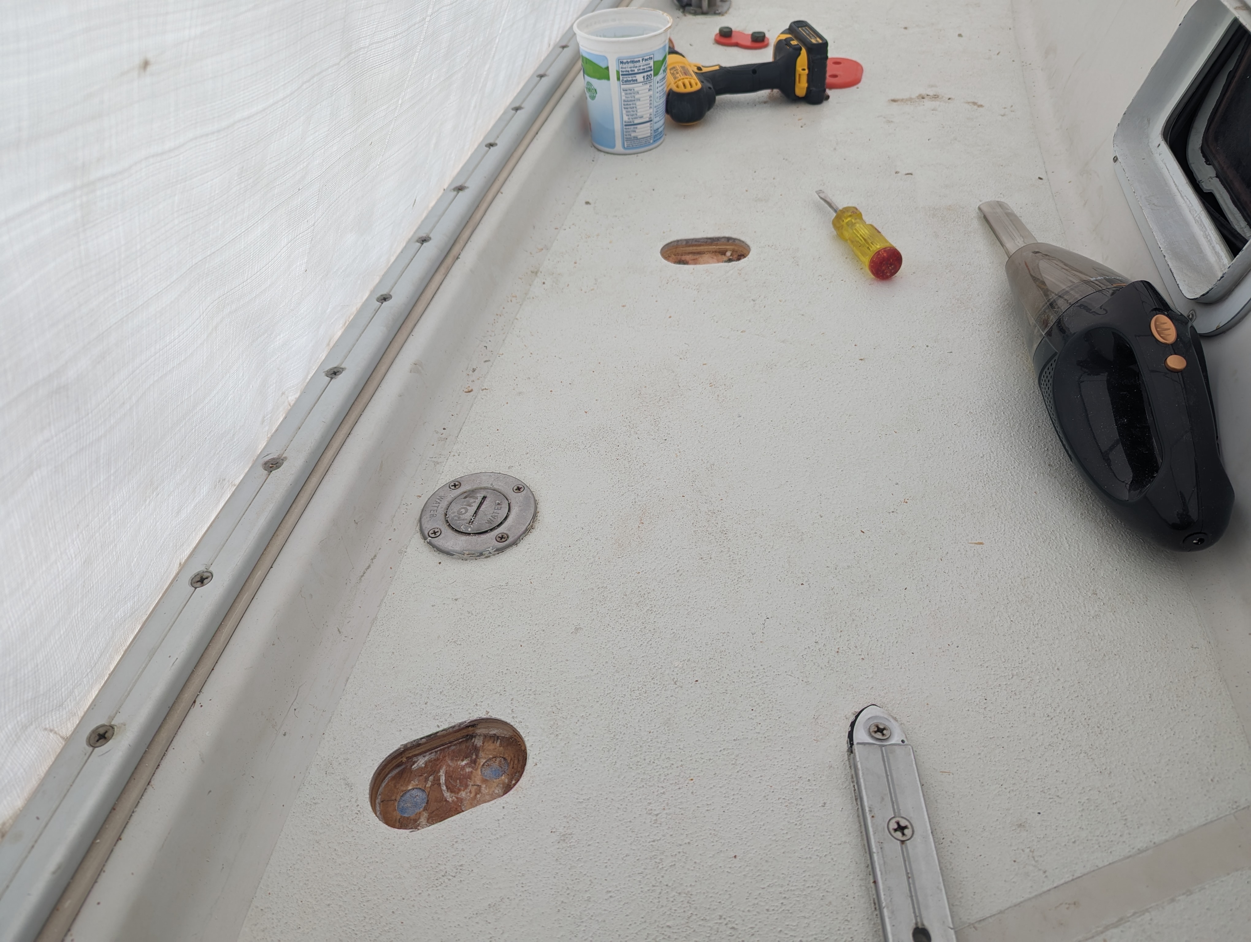
Once that was completed, it was time for the scary part: cutting holes in the deck so the assemblies would fit, leaving the top flange resting on the surface.  Again, I employed a series of 3d printed jigs to locate and mark the cutout area and then used a hole saw and oscillating cutter to remove the top skin and inner core without removing the bottom skin on the underside of the deck.  This was really the only tricky part because it was hard to tell exactly how far to drill without damaging the bottom skin. I opted for a conservative approach and left the cut about 0125" proud of the bottom skin and used a chisel to get the remaining core out.  The good news was that despite clear water intrusion into the boat, the core was not wet (or rotten), just compressed.  After I chiseled out the bottom part of the core and cleaned everything up, I fit the assemblies and was delighted to find that the bolt holes lined up nicely and the top flange covered up the hole.  

The last thing to do was to epoxy it all in. I cut out 2 layers of biaxial fabric to epoxy to the bottom skin, wet them out and laid them in before starting on the assemblies.  For the assemblies, I decided to use Thixo, the ready to go epoxy from TotalBoat that uses a standard caulking gun with a mixing tube to glue everything up. It is much more expensive than raw epoxy, but it keeps mess to a minimum and has a long working life.  With that said, I spent alot of time taping the holes from the underside of the deck and then taping a large area around each hole so I didn't get epoxy all over the deck.  Once ready, I cleaned up all the mating surfaces with acetone and then splooged a bunch of epoxy into the holes and onto each assembly (I did these one at a time).  Then I simply mashed the assembly into the hole until epoxy squeezed out the edges of the flange.  Finally, I cleaned up the squeeze out with a tongue depressor and weighted each assembly down and left for the day.  Once everything had kicked the next morning I pulled the tape and and test fit the chainplate on each 'island'.  I still have to paint them and of course get all the chainplate/tie rod assemblies bolted back in, but I'm really happy the way this project turned out.  I think it's a solid design that will prevent core compression and the raised chainplates will discourage water from entering.


Sunday, May 5, 2024

I Didn't See That Coming

Now that the engine is happily rebuilt and running, I've started planning for what I need to do to get it back in the boat.  This is a huge task that brings the phrase "How do you eat an elephant" to mind.  The answer is of course: "One bite at a time", so the first bite in the process is to get the tarps and part of the frame off to make overhead room for hoisting the engine back in.  

Unfortunately, the deck isn't wateright at this point and that needs to be done before the tarps come off, so I guess the real first bite is: Getting the deck watertight.  The hatches and most of the deck equipment are well sealed and I have re-plumbed the scuppers, but the chainplates are out of the boat and all 7 chainplate assemblies and underdeck tie rods have to be reinstalled.  On paper, it seems like a simple job, but reality always gets in the way.

I pulled the chainplate assemblies out of storage and took them apart to see if anything needed replacing. I should note that these are not your standard stainless or bronze bar chainplates that fit through a slot in the deck and bolt to a bulkhead. These are NavTec chainplates which consist of a deck plate with 2 bolts that go through the deck and connect to an aluminum block which connects to a tie rod which connects to a bulkhead mounted chainplate.  

In theory, they are a nice solution because you don't necessarily need a bulkhead located directly where the chainplate goes through the deck.  They also only have 2 bolt holes that go through the deck and are easier to seal than a slotted bar with a rectangular hole in the deck.  However, what I found when I took apart the chainplate assemblies was less than ideal.

Most of the NavTec chainplate system is made up of nitronic 50 which is essentially a super corrosion resistant stainless steel (better than 316) and a yield strength nearly twice that of 316 stainless.  All of these parts look brand new and will be re-installed as is, but there is an aluminum backing block that ties the above-deck chainplate to the tie rod and on 4 of the 6 blocks, I found serious corrosion that would need to be addressed in several ways.

First, the backing blocks would need to be replaced, but I wasn't able to find a source for replacement so I decided to digitize the blocks and have new ones machined.  I haven't used CAD in years so I was pretty rusty but my son has a Autodesk Inventor license and he helped me get up to speed on the software and once I got the hang of it, I was able to get it done without issue.  To make sure my design was within tolerances of the originals, I 3d printed one of the blocks in PLA to make sure everything fit and once I was satisfied (I did a few iterations), I sent the designs off to a machine shop to CNC them out of 7075 aluminum with a hard anodized coating.

The second, and more concerning issue was why the blocks corroded in the first place. The only way that could happen was if water was making its way down from the deck to the blocks mounted underneath.  A quick inspection of the deck revealed that the core underneath the chainplates on deck was crushed (probably from overtightening the tie rods that attach to the bulkheads).  I was surprised that an area as crucial as the chainplates would have a plywood core and not solid glass, but I shouldn't be surprised by that sort of thing anymore.  The Niagara is a well built boat and a lot of thought went into isolating through hulls from the core, but I feel that they missed the mark with deck fittings.  Time to get to work.

When I re-cored the decks on my Alberg 35, I epoxied in 9 layers of 1708 biaxial cloth where the chainplates went through the deck so no core could be exposed. While this was effective, it was part of a bigger, messier job so I didn't have to be careful about the surrounding deck surface.  For this job I wanted to do something similar, but without having to re-core the whole deck.  After some discussion on several online forums, I settled on the idea of creating oval inserts with flanges made of G10 plate that would replace the existing deck top skin and core material.  The inserts would be .25" proud of the deck and would create an 'island' around each chainplate that would help keep water out of the holes.  I drew up a schematic of what I wanted it to ultimately look like and then did a few 3d prints to make sure my measurements were correct before I started cutting expensive G10 plate for the actual installation.  Next time I'll go into the gory details of cutting holes in deck and epoxying the 'island' inserts into place.