I was happy to receive a package from Xometry (online CNC machine shop) and find the new tie rod blocks I designed exactly as specified and after a test fit I was relieved that everything fit well. They will be replacing the old ones that are in varying states from good to terrible and the 7075 aluminum coupled with hard anodization should provide many years of service.
As you can see in the photo to the left, the old ones (the 2 in the center) are in less than perfect condition and one of them is literally crumbling apart. It was definitely time to replace them. I'm really pleased with how they turned out and I was even more impressed with how easy it is to turn a design into a finished product. All you need to do is load a CAD drawing to the Xometry site, pick materials, finishes, spec tolerances (there are a number of levels going from prototype to mil spec). You can also choose production location (some companies require U.S. made products). Although none of this is cheap (I paid $460 for 6 blocks), it was likely less than what I would have paid locally, and the only supplier that I know of (rigrite.com) has photos of the blocks but no price listed and based on the cost of other discontinued items they have for sale, it would have cost a fortune.Thursday, May 23, 2024
Shiny Blocks and Boat Holes
Sunday, May 5, 2024
I Didn't See That Coming
Now that the engine is happily rebuilt and running, I've started planning for what I need to do to get it back in the boat. This is a huge task that brings the phrase "How do you eat an elephant" to mind. The answer is of course: "One bite at a time", so the first bite in the process is to get the tarps and part of the frame off to make overhead room for hoisting the engine back in.
Unfortunately, the deck isn't wateright at this point and that needs to be done before the tarps come off, so I guess the real first bite is: Getting the deck watertight. The hatches and most of the deck equipment are well sealed and I have re-plumbed the scuppers, but the chainplates are out of the boat and all 7 chainplate assemblies and underdeck tie rods have to be reinstalled. On paper, it seems like a simple job, but reality always gets in the way.
I pulled the chainplate assemblies out of storage and took them apart to see if anything needed replacing. I should note that these are not your standard stainless or bronze bar chainplates that fit through a slot in the deck and bolt to a bulkhead. These are NavTec chainplates which consist of a deck plate with 2 bolts that go through the deck and connect to an aluminum block which connects to a tie rod which connects to a bulkhead mounted chainplate.
In theory, they are a nice solution because you don't necessarily need a bulkhead located directly where the chainplate goes through the deck. They also only have 2 bolt holes that go through the deck and are easier to seal than a slotted bar with a rectangular hole in the deck. However, what I found when I took apart the chainplate assemblies was less than ideal.
Most of the NavTec chainplate system is made up of nitronic 50 which is essentially a super corrosion resistant stainless steel (better than 316) and a yield strength nearly twice that of 316 stainless. All of these parts look brand new and will be re-installed as is, but there is an aluminum backing block that ties the above-deck chainplate to the tie rod and on 4 of the 6 blocks, I found serious corrosion that would need to be addressed in several ways.
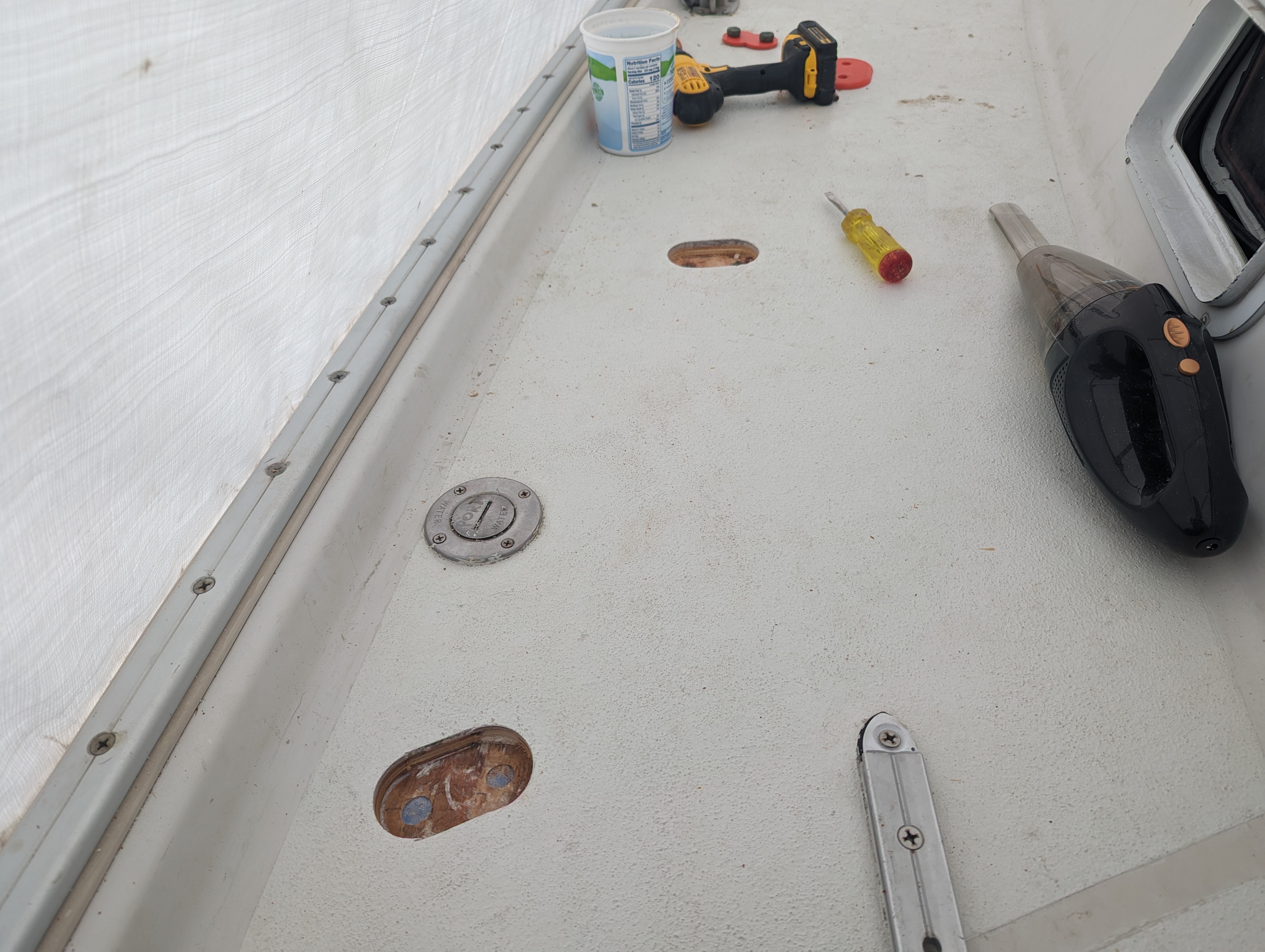
First, the backing blocks would need to be replaced, but I wasn't able to find a source for replacement so I decided to digitize the blocks and have new ones machined. I haven't used CAD in years so I was pretty rusty but my son has a Autodesk Inventor license and he helped me get up to speed on the software and once I got the hang of it, I was able to get it done without issue. To make sure my design was within tolerances of the originals, I 3d printed one of the blocks in PLA to make sure everything fit and once I was satisfied (I did a few iterations), I sent the designs off to a machine shop to CNC them out of 7075 aluminum with a hard anodized coating.The second, and more concerning issue was why the blocks corroded in the first place. The only way that could happen was if water was making its way down from the deck to the blocks mounted underneath. A quick inspection of the deck revealed that the core underneath the chainplates on deck was crushed (probably from overtightening the tie rods that attach to the bulkheads). I was surprised that an area as crucial as the chainplates would have a plywood core and not solid glass, but I shouldn't be surprised by that sort of thing anymore. The Niagara is a well built boat and a lot of thought went into isolating through hulls from the core, but I feel that they missed the mark with deck fittings. Time to get to work.
When I re-cored the decks on my Alberg 35, I epoxied in 9 layers of 1708 biaxial cloth where the chainplates went through the deck so no core could be exposed. While this was effective, it was part of a bigger, messier job so I didn't have to be careful about the surrounding deck surface. For this job I wanted to do something similar, but without having to re-core the whole deck. After some discussion on several online forums, I settled on the idea of creating oval inserts with flanges made of G10 plate that would replace the existing deck top skin and core material. The inserts would be .25" proud of the deck and would create an 'island' around each chainplate that would help keep water out of the holes. I drew up a schematic of what I wanted it to ultimately look like and then did a few 3d prints to make sure my measurements were correct before I started cutting expensive G10 plate for the actual installation. Next time I'll go into the gory details of cutting holes in deck and epoxying the 'island' inserts into place.
Sunday, March 31, 2024
A Big Milestone - A Fitting Day for a Westerbeke Resurrection
It only took about 10 minutes to re-install the fuel injection pump and timing shim, and getting the governor tie rod and spring back on the pump rack in the little hole in the side of the block was surprisingly easy because I had tied on a piece of fishing line onto them so if I dropped them inside the case I could retrieve them easily. Because I've done it several times already, the rest of the fuel system was easy, but time consuming (2 hours).
Once everything was back together and everything checked and re-checked, I rolled the engine over to the shop door, grabbed a pail of water and starting battery and hooked up the ignition panel. My son came over to the shop and we checked to make sure power was going to the glow plugs and fuel pump. It took a bit of time to get the high pressure side of the fuel system primed, but once it was, it fired right up and sounded great. We ran it through the throttle range with no issues other than adjusting the throttle idle setting (a bit too low). Also notable was that there was zero smoke and there was good water flow out the exhaust.
I'm ecstatic that this milestone is complete. My original plan was to get the rebuild done 'over the winter', so technically spring has started and I missed my deadline, but I'm still calling it a win. Of course there's still a ton to do to get the motor back in the boat and installed, but this was a big one.
Here's a link to the YouTube video if you want to hear it purr: It's Alive!
Thursday, March 14, 2024
While I wait
With the injection pump at Diesels Fuel Injection Services for a rebuild (should be completed next week) and the weather still a bit too cold to work on the boat itself, I decided to tackle rebuilding the propeller. With previous boats I've owned, I've only had 2 blade fixed props, but Velorum came with a MaxProp classic which is a 3 blade automatic feathering prop. I've seen them before on other boats at the yard, but never really paid attention or gave them a second look. I'm not convinced that a slowish cruising boat needs a feathering prop but I'm sure I will appreciate the additional power a 3 blade will deliver and not be concerned with the drag that a fixed 3 blade would have on performance.
Anyway, the prop was in a box in several pieces and covered in grease and barnacles, so I wanted to clean it up to assess if it needed to be serviced. I started by degreasing all the parts and doing a rough scrub to get as much old marine growth off as I could.
After the first round, it really didn't look any better than when I started except there was less grease. 'Less' is the keyword here because even the industrial strength grease remover I was using didn't seem to do much other than spread it around. Close to a roll of paper towels and more degreaser finally proved effective and I was finally able to handle the parts without my hands turning black.
Next, I tried a brass wire brush to get the rest of the barnacles off and finally resorted to a wire wheel, but it still looked pretty sad. After a little online research, I picked up a gallon of vinager and soaked all the parts in a bucket overnight. That seemed to loosen up the remaining barnacle 'roots' and I was finally down to a mottled brownish bronze finish.
I felt like I was finally making some progress (albeit slow). My wife suggested I use Bartenders Helper to get it shined up. Apparently, it's a powdered form of oxalic acid with some sort of abrasive in it. Once again, I'll admit my wife is brilliant, that stuff works great. Just shake some on the part and scrub it with a wet sponge and it works wonders. After a few rounds of that stuff, it looked great (at least the pieces did).
Now it was time to put it all back together and hope all the pieces were there. I found that PYI Inc is the distributor and service center for MaxProp in addition to the very popular PSS dripless shaft seal (I'll be installing that once the engine is back in the boat). They have a great site and even though the MaxProp Classic (the model I own) is discontinued, PYI still services them and sells parts. I contacted the service department and they got back to me with all the info I needed along with a detailed pdf on assembly. They even took the time to run Velorum (displacement), along with engine size, and transmission gear ratio to give me a recommended pitch setting for the prop.
Putting it back together was pretty straightforward given how precise everything needs to be in order to have a smooth, balanced, and powerful propeller. It's really a lovely piece of kit and the engineering is downright elegant. It's simplicity is deceiving, it really has a difficult job in a very unforgiving environment. Once I got it back together for a test fit (once it goes back on the boat it will be stuffed with grease like a turkey), it looked amazing and operated smoothly. I was told by support that it should have a tiny amount of play, but more than an 1/8" and I should think about a rebuild. Fortunately, everything checked out and it's in remarkably good condition. I don't know the history of this prop, but it should last me for some time as long as I keep the internals greased every year and don't back it over a rock :)
Sunday, March 3, 2024
Rattle Can Rebuild Part X
With everything back together and after lots of electrical testing, it was time to fire it up. I wired up the battery to the starter solenoid, plugged in the new Admiral panel and oil/water alarm harness and got a bucket of water to run through the raw water pump. I turned the key and hit the preheat button for 10 seconds to fire up the glow plugs and then pressed the start button. The engine cranked and cranked, but wouldn't catch. I stopped and re-checked everything and repeated the process. Still nothing. The engine cranked fine, but wouldn't catch.
First I tested that the glow plugs were working; they were. Then I moved onto the only other possibility: the fuel system. I knew that fuel was making it through the low pressure pump and into the secondary filter and to the injection pump. However, when I cracked the fuel line at one of the injectors, I found no fuel... It appeared that the injection pump wasn't working properly, but I spent a day or two scouring online forums to definitively prove that the injection pump was the problem. I found my answer quickly on the Cruisers Forum where one of the users (SkipperPete) gave me the answer I needed. Yes it was more than likely the injection pump.During the rebuild, I studiously avoided the injection pump because I naively hoped that it would run after 10 years sitting without running and with old fuel in it. An additional problem with the injection pump is that it is difficult to get at and in order to remove it, you have to disconnect a very fiddly spring and tie rod that attaches the govenor to the rack on the pump. I honestly thought it was 'above my paygrade' and seriously considered putting the engine on a trailer and taking it to a diesel repair shop.
I'm glad I didn't and the help I got from the Cruisers Forum gave me the courage to tackle the project. I did have to disassemble the entire fuel system surrounding the injection pump to get at it, but at this point I was sure that I could reassemble it again without too much trouble (but I took lots of photos). However, in the end, pulling the injection pump wasn't actually that bad and I probably saved at least $500 just in the disassembly process. Now I have the pump out of the engine and will take it to a injection pump shop to have it rebuilt. Yes, this will be expensive, but this is something that is not for amatuers and requires specialized high pressure testing equipment and expertise that I just don't have.
So tomorrow morning, I'll be dropping it off at Diesels Fuel Injection shop to have them rebuild the pump. I used them to rebuild the injectors (which also require specialized equipment). Hopefully, my next post will include a video of the engine running. Below are a few shots of the injection pump:
Monday, January 15, 2024
Rattle Can Rebuild Part 5
Since the end of August until late December, I had been singularly focused on boat projects, but over the holidays, I decided that I needed a bit of a break. I tend to get hyperfocused on projects and everything else falls by the wayside, but I was on schedule for the engine rebuild so it was time to shut the project down for a few weeks. I'm glad I did, I really needed a break but didn't realize it at the time.
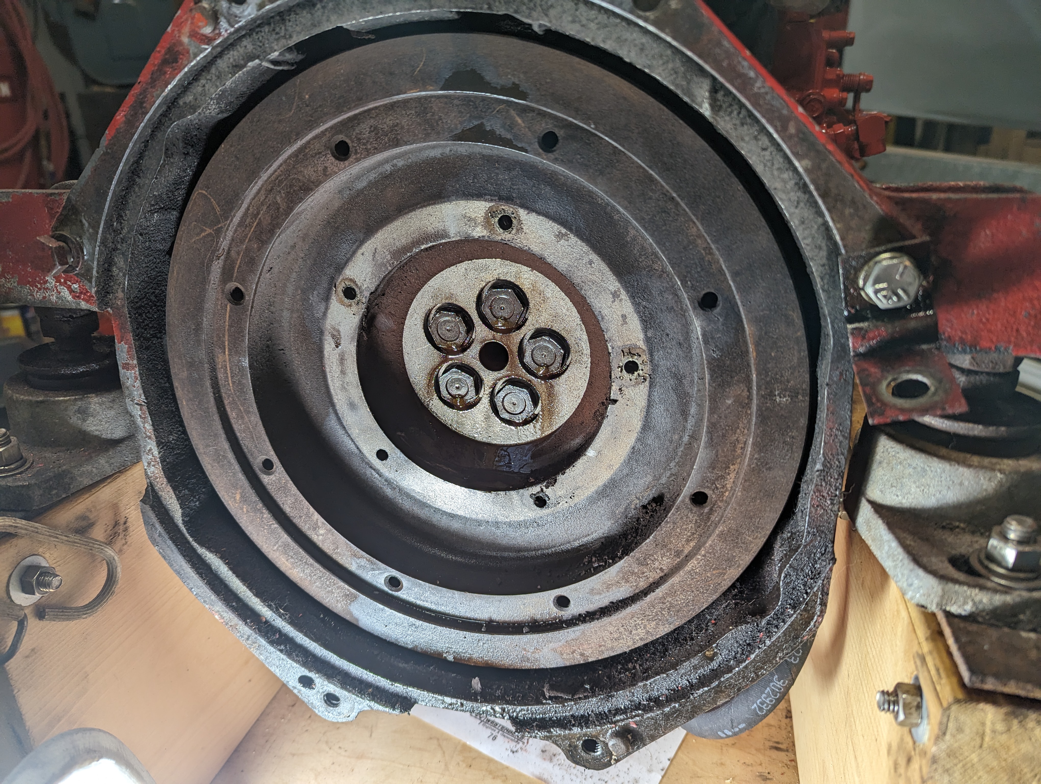
Now that I'm back I was able to tackle one of the bigger projects of the build and hopefully will be about as deep as I go on this motor. When doing the initial inspection and research on the engine, I noticed a bit of oil staining on the bell housing underneath the flywheel. After a bit of googling on the usual forums, all signs indicated that it was a problem with the rear main seal.
In theory, it's a very simple process, but this task was quite the struggle. First of all, I had to take it off the stand (it bolts onto the bell housing). I lowered the engine down onto the rolling cradle to secure it before removing the damper plate (this connects the the transmission and dampens shock loads from the transmission to the crankshaft and vice versa). This part was straight forward, remove 5 allen bolts and it pulled right off. I was really amazed that I didn't strip or break them off because they were very tight. This is where things got difficult. With the damper plate off, the bolts that fix the flywheel to the crankshaft were exposed. They weren't rusty or corroded, but quite dry and Very tight. Initially I tried the 19mm bolts with a standard 1/2" drive socket wrench and couldn't budge any of them. Next I tried my cordless impact wrench. Nothing. Finally, I slathered multiple coatings of PB Blaster on each bolt and called it a day.
Saturday, December 23, 2023
Rattle Can Rebuild Part 4
As I go through the engine I'm looking for things that don't look right and it didn't take me long to find something. The picture above is the raw water pump drive gear. Basically, it's a gear that's driven off the crankshaft through a series of gears in the timing case and the slot in the middle is where the water pump impeller shaft inserts into. The arrows in the picture show where the slot is gouged or worn from the water pump impeller shaft hitting it. I'm not sure why this happened, but maybe it's normal wear for an engine with 974 hours.
Fortunately, I have a new drive gear and bearing set, but I wasn't sure how to get at it. The Westerbeke W27 schematic indicates that it is accessed by removing the timing case (or at least I thought it did). The timing case is not something I want to get into, because in order to take it off, the govenor spring needs to be disconnected from the high pressure injection pump and it's accessed through a small plate on the side of the engine. The manual states several CAUTIONS about how fiddly this is and if you drop the spring, you are screwed. I'm certainly not a diesel mechanic, and warnings like that scare me.
I did a bunch of googling and forum posts asking around about how to get at the drive gear and because each engine does things a bit differently, I got a bunch of opinions that were all over the place. Finally, I emailed the picture above to Hansen Marine Engineering and asked 1. Is this bad, 2. If so, how do I replace it. Fortunately, they got back to me within a day and said this is a common problem and it should be replaced, but to do so simply requires removing the bearing housing that the raw water pump bolts to. Yay, no timing cover removal!
With my newfound knowledge, I got to work and unbolted the bearing housing and within 5 minutes I had the old gear in hand. To reinstall, I just had to seat the 2 interference fit bearings on either side of the gear. Of course, you can just drop them on, they have to be pressed on. I didn't really want to take it to a shop and I didn't want to hammer them on (and risk screwing up the bearings) so I tried a fun trick that I had used before when putting bearings on my tractor mowing deck spindle.I put the gear in the freezer overnight and the next morning I heated up the oven to 275F and put the bearings in for an hour. The theory is that the shaft of the drive gear will shrink slightly in the cold and the bearing races will expand with the heat. Once everything was sufficiently hot and cold, I pulled the gear from the freezer and the bearings from the oven and with a hot mitt slipped them on. One side slid on with little effort and the other side took a few taps from a plastic mallet on the inner race but it worked and once the temps equalized, the bearing were tightly fitted onto the gear.
Now that the bearing and gear assembly was all together, reinstallation was just a matter of reinserting the gear and bearing housing assembly into the back of the timing case and bolting it back on with a gasket. Super simple, but a lot of hand wringing along the way. I might just become a diesel mechanic yet!Next up, I assembled the actual raw water pump which consists of a housing (part #048080), the impeller shaft, 2 bearings, and a series of seals and washers to keep everything watertight. Fortunately, the schematic is very good for this assembly so it wasn't difficult. I still have to paint the pump housing, but once that's done I can bolt it onto the drive gear housing and call it a day.