Monday, March 17, 2025

Hatches, Ports, Handrails, and Refinishing Dorade

As part of my effort to get the top of the boat waterproof so I can remove the cover for the engine install, I started knocking items off the list that I posted last week.  We had some warmish temps over the past few days so I was able to get all the opening hatches (5) and opening ports (6) regasketed.  The hardest part of the job was getting the old gasket and sealant out (see last post for details).  

Once the hatches and ports were prepped, installing the new gaskets was actually pleasant.  Just cut the correct gasket based on the perimeter of the hatch channel, lay in a bead of Silaprene and press the gasket in place.  Once it's seated, just close the hatch and clamp it down.  24 hours later the Silaprene had cured and the gaskets were locked in place.  Easy peazy and the Silaprene was nice to work with.

Moving on to other holes in the deck, Steph and I tackled the handrails.  I had removed the handrails last fall and brought them home over the winter to clean up and re-varnish (12 coats) before re-installing.  Originally, I had big plans to change the way they were affixed to the deck, but never got around to it.  The handrails as designed were screwed in from the underside of the deck with 2 woodscrews in each mounting point.  Hinterhoeller did do a nice job providing holes in the headliner to access each screw, but the rails really should have been through bolted for a number of reasons.  The original design team incorporated a lot of well thought out ideas for the Niagaras, but using wood screws for handrails was not one of them.
  • Through bolting provides a much stronger connection than wood screws.
  • Allows easier mounting of the rails since the longer handrails are curved and need to be bent into place.  
  • Gives more sealant options. I'm a big fan of butyl tape for sealing through bolted connections, but you can't provide enough compression force for butyl tape with wood screws
Anyway, I settled on using the woodscrews again and it was a bit of a bear to get done.  Starting at the aft end, we mounted the smaller handrails (4 mount points) without too much issue because they were straight and didn't have to be bent in place.  We taped off the area around the rails and I laid down a bed of 3M 4200 sealant on the rail and then set it in place.  Steph was on deck holding the rail in position while I screwed up from the bottom, gradually tightening each one.  The larger handrails (7 mount points) were much trickier because Steph had to hold the rail in place until I got the first 2 mounts screwed in.  Then she carefully bent the rail inward and I moved to the next one.  The hard part was keeping the next few mounting points off the deck so the sealant didn't smear everywhere.  We managed, but I can't say that it was my best job.  They are solid and should be watertight, but the sealant looks a little janky in spots.

Handrails installed


Like the handrails, I brought the dorade vent home to clean up and varnish over the winter.  When I removed it last fall, it was screwed directly to the deck and appeared to be penetrating the cabintop core.  When it came time to reinstall, I overdrilled the holes and filled them with slightly thickened epoxy and let it cure.  Once cured, I re-tapped the holes so there would be no water intrusion into the core going forward.  Tapping around the 4 mounting points didn't reveal any core issues and when I overdrilled the holes, the wood chips coming out were dry, so I think I caught it before it became a problem.   

Reinstalling was just a matter of applying sealant where the screws penetrate and screwing the box back into place.  Then I sealed the lexan cover with silicone (clear) and screwed that down along with the new cowl.  


Wednesday, February 26, 2025

Back to Work

We had a pretty cold winter in NH that kept me off the boat for a few months other than to check in to make sure the cover was holding up. However, the planning and scheming never stopped in my head and did do a few minor projects over the past few months.  The planning I did was really a logistics exercise for the engine installation and I found a surprisingly large number of things that need to be done before the engine actually gets hoisted into place.  Additionally, some of the items on the list are temperature dependent and have to be done once the temps start to rise.

So in a nutshell here is what has to be done (in rough order):

  • Waterproof the top of the boat (The cover has to come off during engine install)
    • Replace all gaskets on hatches and ports
    • Rebed fixed windows 
    • Rebed deck hardware 
    • Finish installing and bedding chainplates
    • Cover engine control cutout
    • Cover instrument cutouts 
  • Prepare engine compartment (temp dependent)
    • Assess engine beds
      • Add additional glass if needed
    • Paint compartment
    • Re-install strut (maybe temporarily to aid in shaft alignment later)
    • Clean up and re-install exhaust and bilge pump fittings on stern
    • Re-install water lift muffler and exhaust pipe to transom
    • Choreograph engine installation plan
      • Once the engine is lowered into companionway, how to get it onto engine beds
  • Installation
    • Remove cover
    • Remove framing so crane can lower engine
    • Schedule crane (the farm where I keep the boat has a myriad of big machinery, but I need to coordinate with the owner)
    • Measure companionway opening and determine what needs to be removed from engine for install
    • Run engine at shop and drain coolant (oil too?)
    • Move engine from shop to boat and prep for hoist
    • Hoist engine into boat
    • Get engine on beds.

There's a lot of little things that won't take long and I know what to do, but there are a bunch of unknowns that I haven't done before and they are going to take some thought to do it right.  Of course, after this is all done, I'll have to re-install the transmission, get the shaft aligned and installed, and install the new engine control panel, but I'll tackle that when I get there.  

Now that I'm seeing some cracks in winter's grip, I've started on the waterproofing step by removing all the hatches and bringing them home to replace the gaskets.  Most of the hatch gaskets are pretty old and cracked so I ordered 3/8" and 1/2" round neoprene gasket material (Trim-LOK rubber cord seal) to replace what was there.  Removing the gaskets is tedious and slow, but not difficult.  The gaskets themselves come right out, but the sealant (Silaprene) is tenacious and I found that the best technique is to use a rounded wood cutting gouge and get under the sealant then slowly pull it up as you work your way along around the hatch.

It's still a little too cold to re-apply the gaskets. Silaprene requires 40 degree temps and right now we are in the 30's.  Once we get a few warm days in a row, I'll re-install all the hatches, apply new sealant, seat the gaskets and then close them up (that will give even pressure to the gasket on the hatch so it can seat and cure properly).  I haven't tackled the 4 opening ports yet, but that's on the list for this week.

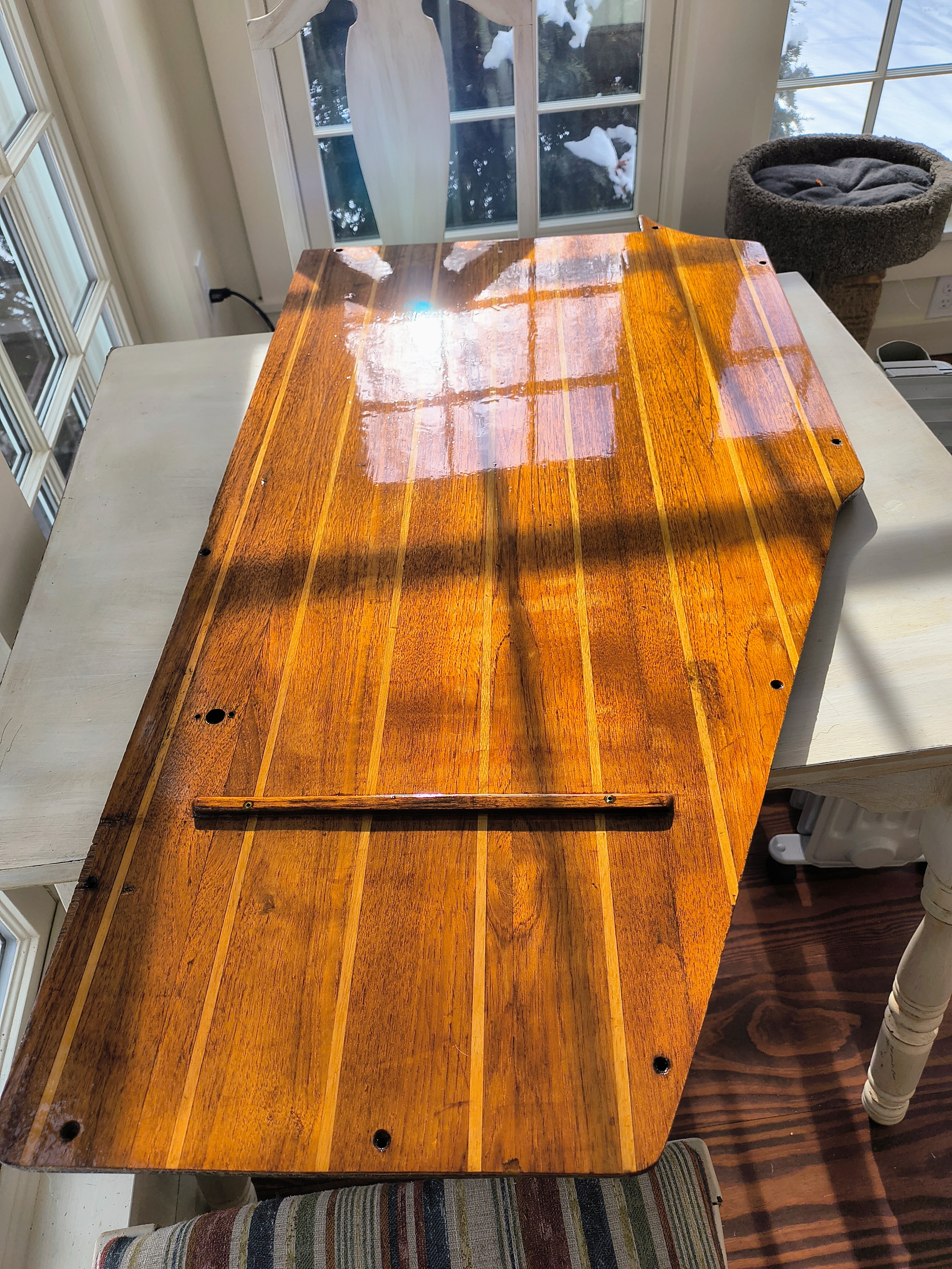
In other news unrelated to the engine install, I revarnished the cabin sole section at the base of the companionway steps.  The existing varnish had peeled up in the corners and it just looked ugly.  I brought the section of cabin sole home and using a heat gun, stripped all the old varnish off and then gave it a quick sand with 220 grit to get any remaining varnish off.  I followed up with 12 coats of varnish.  I think it looks pretty good, and I'm hoping it won't make the rest of the cabin sole look shabby.  The other sections look good to me, but once installed I'll know if the others will need to be done as well.  

Finally, I don't like the exposed location of the engine controls, they are in direct sun and initially I was going to build an inset for the controls that would keep them somewhat protected when not in use, but I ended up designing a cover (AutoDesk Inventor) that I could snap on when not in use (most of the time).  As we speak I'm printing the prototype on my 3d printer using  TPU filament (95A durometer).  TPU is a flexible filament (like rubber) and should be a decent solution.  Time will tell how long the TPU will hold up in the sun, but even if it lasts a summer, I can alway print another.


Wednesday, November 27, 2024

Masthead Removal

The weather is getting colder, but I keep finding excuses to start a new boat project.  In reality, I'm having fun and unlike last year when I rebuilt the Westerbeke over the winter, I'm a little worried that I'm going to run out of things to do this winter.  The majority of the systems are installed and it won't be long before it will be too cold and snowy to work on the boat, so I'm doing a bit of hunting around to find a few projects that I can do in my shop over the winter.  

I can't really get going on the rigging work because I'm going to have to spend a bunch of quality time with the old standing rod rigging laid out at the mast to get accurate measurements for the new wire rigging and I'd really rather not have frozen fingers for that. It can wait till spring. However, I was standing by the mast the other day pondering how I was going to get the new radio antenna wire snaked out the side of the mast up near the masthead when I noticed that it looked like the masthead was removable.  

After consulting with the Niagara 35 Owner's Group on Facebook, I decided that this would make for a good project if I could get it off the mast.  The sheaves are probably pretty tired and I could have new ones made and replace them over the winter and clean up the masthead. The question however, was whether or not the assembly was fused to the mast from years of sitting outside or if somebody had decided to glue it all together with 3M 5200.  

Today happened to be pretty nice, so I figured I'd give it a shot.  There were 3-7/16" stainless steel bolts on each side holding the assembly to the mast, and I was pleasantly surprised that every single one of them freed up without any difficulty at all.  The only problem I had was that someone had installed the radio antenna bracket very close to one of them and had to switch to an open ended wrench to get that one off because there wasn't room to get the socket on.

Once I had all the bolts out, I gave the assembly a tap and was really surprised when it actually moved and wasn't corroded to the mast. Stainless steel and aluminum don't mix very well when wet and if you don't apply an anti-seize compound (Tef-Gel is one brand) when you thread in the stainless bolt, you can end up with a corroded mess and the aluminum always loses. Somebody clearly installed this the right way. 

As I pulled the masthead out, I labeled the substitute halyards and took a bunch of photos so I could reverse the process when I reinstalled. Honestly, I couldn't believe my good luck. Boat projects never take just 1 hour with no swearing so I'll chalk this one up as decidedly pleasant.  I haven't pulled the sheaves out yet or inspected them closely, but I will probably replace them for good measure regardless of condition (TBD). The big bonus for this effort is that it will make rewiring the top of the mast infinitely easier.

UPDATE: I took apart the masthead this morning and was pleased to see very little wear on the sheaves themselves, the bronze journal bearings, or the stainless steel axles. The axles fit snugly through the journal bearings with no play. The sheave themselves are a combination wire/rope sheave with a groove in the bottom to accommodate wire, but it was clearly never used, so looks to be a rope only boat (unless these sheaves have been replaced at some point). So I guess this is one area I won't have to spend money for replacements. I cleaned everything up, re-greased the axels with lithium grease and put it all back together.


Sunday, November 3, 2024

Fire in the Hole (and other project updates)

I'm really pushing it on the weather now, but it has been warm enough to knock off a few more projects before I'm totally shut down for the winter.  To be honest, now that I've pushed the engine reinstall until next spring, I'm pretty close to finished with all of the systems.  With that said, here is the high level list that still needs to be done before Velorum gets wet again (no particular order):
  • Mast rewire - Steaming light, foredeck light, anchor light, tricolor light, wind transducer, VHF antenna. 
  • Mast standing rigging - Replace rod rigging with wire and all associated hardware.
  • Rebed all deck hardware - All of it, everything needs to be pulled, rebedded with appropriate sealant with new backing plates where needed.
  • Windlass install - I may or may not get to this before I go back in the water, I have the windless (Maxell RC8), but the wiring to the bow will cost close to $1000.
  • Autopilot - I still have to sort out the wiring and reinstall properly. 
  • House batteries - I haven't purchased the new batteries yet.
  • Refrigeration - I pulled out the old Grunert engine driven refrigeration.  It reportedly worked when the boat was pulled in 2013, but there are way too many moving parts and it takes up a lot of room in the engine compartment.  I will be replacing with an air cooled Isotherm GE150.  It's much smaller, reliable, and draws very little current. This is something that can wait until after splashing the boat because it's a pricey item and funds are getting low in the coffer.
  • Starting battery - I'm relocating that to the engine room now that the engine driven refrigeration has been removed.
  • Inverter - 2000w wired into AC circuit.
  • External battery charger - I have it, but probably won't use it much because I'm rarely on shore power
  • Engine reinstall - Last but not least....
Ok, I'm overwhelmed again, but I have to keep pushing forward. Focus on the next job and get it done. One of the last electro-mechanical systems that needed to be installed was the propane system.  Originally the boat had a Paloma on-demand propane water heater, but I replaced that with and Isotemp 15 liter hydronic water heater.  Interestingly, according to ABYC standards, the only LPG connections on a vessel should be in an approved tank box (with overboard discharge) and the appliance itself.  Velorum had a single connection from the tank box and then a tee junction in the bilge where the one line went to the stove and the other went to the water heater in the head.  Certainly a no-no by today's standards, but I'm not sure what they were in 1986.  Anyway, with the Paloma gone, it was just a matter of plumbing the propane line from the tank box located behind the wheel in the stern of the boat to the Seward Hillerange 3 burner stove.  

I also had to install the solenoid (Xintex SV-1) in the tank box and wire it to the Xintex S-2A controller located at the wiring panel.  This turned out to be dead simple because I had already done the hard work of running the wiring up to the tank box (all the other controller wiring was completed). So all I had to do was connect the 2 wires to the solenoid and plumb that between the regulator and the downstream propane line.  

The hard part was running the propane line from the stove back to the tank box. Using my finest boat yoga skills, I spent the better part of 4 hours in the aft lazarette routing and securing 20 feet of propane hose from the stove back to the tank box.  It really is stupid that it takes so long and requires so many contortions, but it is what it is.  I signed up for it and knew what I was getting into. 
 
Once the hose was at the tank box, I screwed all the pieces together with gas rated teflon tape and secured the assembly in the box.  I brought one of the 10lb tanks over from the house and connected it up before realizing that I hadn't installed the overboard tank box drain hose to safely drain any propane gas out of the boat and not into the bilge.  So it was back in the lazarette for some more contortions and choice words to fit the hose and clamp it tight.

Finally, I fastened the other end of the propane hose to the stove and soap tested all the connections.  I didn't find any leaks so I decided I should try it out. I turned on the main panel (I have a DC converter connected to an inverter to power the DC side).  Next flipped the stove switch and waited for the Xintex controller to do its system test (I installed 2 propane detectors in the boat when I rewired everything).  Once the controller went green, I turned on the solenoid button on the controller and fired up the stove.  No big booms, just the satisfying blue hue from the burners.  Yay!  I still have to reinstall the plywood partition in the tank box that keeps 2 tanks in place, but I'm going to call this job about done.


Thursday, October 17, 2024

A Fun End of Season Project


I don't have much time left before winter shuts down work on the boat, so I'm trying to make the most of it before it gets too cold.  It may seem like I'm randomly picking projects to cross off the list, but I do actually have a plan (subject to change of course).  I'm trying to work from the bottom up in most cases but have found that certain projects (like the wiring and plumbing) logically should be done before others. 

Now that I have both the wiring and plumbing completed (mostly), my next step is to start prepping for the engine install.  Originally, I was going to put the engine back in this fall, but I decided that keeping it in my heated shop until spring makes more sense. First of all, I won't have to winterize it and second, I can run it every few weeks or so during the winter to keep it happy.  

With that decision made, there were a few things I'd like to take care of before winter and the one that made the most sense was to get a start on the engine install and get the fuel system fully ready to go.  I had done a bit of work on it over the summer by running the fuel fill hose through the compartment where the water pump is now housed, but not much more. 

Most of the prep work to install the new tank was done for me other than getting the bilge painted (I did this last fall).  I basically had to plop it in place and bolt it down.  The original tank was held in place by a single wood bracket that spanned across the tank and mounted on a plywood 'rib' that was glassed into the hull.  I decided that was a little bit sketchy given the fact that 37 gallons (new tank size) of diesel weighs more that 250 pounds and even though the tank is wedged in pretty nicely, I don't think that wood bracket and the floorboards screwed down would hold it in place if something major happened (a knockdown or outright roll).  So I purchased some 2x2" aluminum L channel, cut a 2 foot section to through bolt to the forward rib.  Because the fuel fill and vent access the tank from the aft end, I cut 2 smaller pieces of L channel and through bolted them to the aft rib on either side of where the hoses run on top of the tank.

Next up, I spent a stupid amount of time fiddling with npt fittings to make sure they fit the fuel line and return (I ordered marine grade A1-15 fuel hose for both the fuel line and return).  The previous owner had planned on installing a dedicated fuel polishing system that he could run on demand that routed to a separate fuel water separator and had 2 extra tank ports installed. It's good idea, but I'm going to hold off on that and do it once the boat has been in the water.  In the meantime, I capped off those tank ports.  The fuel feed line I added an aluminum shutoff valve (3/8" npt male to 3/8" barbed hose end) onto the 3/8" npt aluminum elbow. For the return line I installed a 3/8"npt male to 1/4" barbed brass elbow.  I wanted to use aluminum (to avoid galvanic corrosion), but I couldn't find a fitting in aluminum that had the low profile clearance I need because the tank is within 2.5" of floorboards once installed.  I'll keep an eye on that, but I should note that I used permatex fuel grade sealant on all the connections, so that should effectively separate the dissimilar metals.

Finally, my son and I thought it would be fun to incorporate arduino devices on the boat, and the fuel gauge seemed like a perfect first project.  The tank came with a resistive fuel sender that is essentially a float mounted to a potentiometer.  When the tank fills up, the float rises with the fuel level and the resistance changes as the float moves toward the top. Knowing that arduino devices are very good at taking signal input I could use a python program and a OLED screen to convert the values to a 0-100% scale and print it out on the screen.  

I didn't want anything complicated that would require running more wire (I'm done with that) and decided to use battery power and a momentary switch to take the reading and then turn off.  The amount of battery consumption is so small that it would take quite a long time to run out of juice.  I bought an 'arduino nano every' board, a tiny OLED display, and a momentary switch for about $25 total and got to work.  It will be mounted on top of the fuel tank below one of the removable floorboards on the centerline of the boat.  In all the boats I've owned over the years my fuel gauge was always a grimy wooden stick and compared to that this will be quite the luxury.

We wired up the circuit on a breadboard and wrote a simple program to convert the incoming values into a 0-100 scale. My son added code for a small graph to show the level visually as well.  Once we had it working, I designed and 3d printed a simple box to house the electronics and after a few tries (my son thinks I'm terrible at prototyping) we were able to fit everything in and got it installed.  It certainly looks homemade, but it was a fun project and enjoyed working on it with my son.


Sunday, September 22, 2024

Water System - Check (almost)

 It's been 1 year since I purchased the boat and had it hauled to its current home at Glines Farm and I've spent a lot of time trying to figure out the best location for the new water fresh water system.  The original water pump was stuffed under the sink in the head compartment and must have been a bear to service and maintain.  Additionally, the hot water side of the system was an on-demand propane system that was outdated and dangerous by today's standards (my understanding is that insurance is hard to come by with these types of systems).  So that had to be replaced with a more modern hydronic system (heat exchanger powered by engine water hear or 110v AC).  

Luckily for me, Velorum as I bought her was a clean slate; all the systems had been removed so I had the luxury of being able to imagine the best (IMHO) location for a new water system.  The location of the tanks was the exception, the new 40 gallon tanks would be located under the port and starboard settees just as the original.  For the rest of the system, my only criteria was that it be easily accessible and that I wouldn't have to contort into ridiculous positions if/when the system needed servicing.  

There were a number of possible locations, but I ultimately chose to install the system underneath the port settee just forward of the navigation table and aft of one of the water tanks.  This space is close to ideal because:

  • Access is great. If I remove the settee cushion, there is a large panel that lifts off to give me full access to every component in the system.  There is also a decent sized hatch below the settee cushion that would allow me to mount a valve to switch tanks.
  • Proximity to the engine.  With hydronic heating systems, hot water from the engine is circulated through a heat exchanger in the tank (I chose a 20 liter tank) to heat the fresh water. The closer to the engine you are the better the efficiency.  This puts me within 6 feet of the engine.  I could have located it aft of the engine in one of the lazarettes, but this would defeat the easy access rule I wanted.
Next up was designing the actual system.  I'm using the term design fairly loosely here; I just needed all the components (tank valve, pump, filter, accumulator tank, water heater and exit runs) to fit in the space I had, so my design was nothing more than a rudimentary sketch on a sheet of paper.  Beyond that, I just made it fit, paying attention to accessibility of each connection and component as I went along.  
I glued a piece of plywood with 3M 5200 to the hull to mount the pump, filter, and accumulator tank in the compartment.  Then I discovered the wonders of pex tubing and specifically Watts Aqualok pex connectors.  They are all plastic (no corrosion) and make connecting 1/2" pex tubing together easily with no plumbing skills at all (I have none).  Best of all, they can be disconnected without any special tools should something need reconfiguring. 

For the installation, I began with the water tanks and worked my way downstream.  It was a little tricky getting all the pex tubing in place and I had to drill a few holes in the bottom of the compartment for the pipe runs to exit.   

I dry fit everything and made sure it would all be easy to access and maintain once fully installed. There were a few adjustments along the way when I realized that the 1.5" fuel fill hose had to run through the same compartment, but other than that everything fit nicely.  

From there I moved onto the service lines that exited the compartment. Using blue for cold and red for hot should make troubleshooting in the future a bit easier.  I kept the runs as straight as possible for each of the three service points (galley faucet, head faucet, and shower) and secured the pex tubing every 12" or so.  

I teed the main hot and cold lines about 6 feet from where they exit the compartment where the pump, water heater and associated equipment was located.  Going aft will be the service to the galley faucet, but I won't complete that until the engine has been reinstalled because the galley peninsula that houses the sink has to be removed for the installation and having all the sink and faucet equipment installed would make removal unwieldy.

From the tee going forward the line tees again for the shower service and continues straight for the galley sink service.  Routing the shower service proved to be a difficult task, but I was able to find a route that didn't require cutting more holes in furniture.  


Once the pex tubing was roughed in, I reassembled the head vanity and installed the sink and a new faucet.  From there it was a simple matter of ordering the right Watts Aqualok fittings so the sink could be plumbed for hot/cold water and connect the drain to the seacock.  

That left me with the shower.  I ordered a Scanvik 16205 low profile shower mixer and a random handheld shower from Amazon. When they arrived I finished the pex routing inside the hanging locker in the shower compartment. I routed the tubing up along the bulkhead wall and over the top of the cabinet entry so I wouldn't loose any space in the hanging locker for towels or other items.  I enlarged the hole where the original shower mixer was located and installed the mixer and service lines and then connected the hot/cold to the appropriate pex lines.  Finally, I connected the handheld shower head line to the remaining service line on the mixer and installed the hanger bracket.  


I won't be testing the system for leaks until I install the service to the galley once the engine is in (probably next spring), but I'm pretty certain I did a decent job connecting everything and having used pex connectors in the past in my house, they seem to be fairly fool proof (we'll see).  While the project isn't quite done yet, I can safely say that the head and shower compartments are 100% finished.  


Monday, August 5, 2024

Hot Boat Yoga

I suppose I could have picked a better time to do the electrical job, but because the full re-wire was not initially planned, I had to get it done when it was absolutely stifling inside the boat.  Most of the work took place early in the morning before it got too hot, but this afternoon I decided I just wanted it done, so heat be damned.  

I won't go into too much detail on running wire, but I decided to run dedicated duplex wiring to each appliance to make it easier to troubleshoot down the line and to provide additional chafe protection from  the outer sheathing.  All the cables were secured and bundles in runs with zip ties and split loom conduit where feasible.  

For the wire size, all the pumps and anything that draws over 5 amps I used 10 AWG marine tinned duplex Ancor wiring.  For the smaller appliances such as navigation lights, shower fan, bilge blower, and the holding tank monitor, I used 16 AWG.  The wiring running to the mast (and in the mast) is marine triplex 16AWG that shares a common ground.  The reason I did this is because the 2 appliances on the mast are combination units (anchor/tricolor lights and steaming/foredeck lights).  It also adds more protection because it has a very thick sheathing and is generally more convenient than running single wires.

All told it took me close to three weeks and close to 300 feet of wire working for a few hours before work each morning.  A lot of time was spent trying to figure out the best run for a particular wire or bundle off wires.  Even more time was spent trying to wiggle into corners and underneath the cockpit sole to run and secure the wiring.  Once I found a suitable location to run the wiring, I would pull from the spool starting at the navigation station and loosely set it.  Then I'd work my way back to the navigation station securing the run with zip ties and screwed to bulkheads.

Once all the wiring runs were done, it was time to start the real work: connecting everything to the terminal blocks and negative bus bar and ultimately to the new distribution panel.  It was a pleasant change from the boat yoga exercises I had been doing and it involved mostly sitting at the nav station, stripping wire, crimping connectors and then heat shrinking tubing over them.

Of course, all boat work takes longer than I think it will and making all the connections, securing the bundles, testing, labeling and documenting took about a week (mornings with a few longer sessions).  All the wires are labeled and I created a back panel wiring schematic that I'll probably print and laminate to keep on the boat in case the shrink wrapped labels come off.

I still have work to do though. The navigation instrumentation isn't currently installed in the boat yet and that will be a while, so I've reserved most of the right terminal strip for those items and a few more for future needs.  I also have to connect the new navigation lights, bilge blower, and shower fan to the newly installed wire before I'm fully done (as well as a few custom labels that I ordered for the distribution panel), but the bulk of this job is done.  

Here are a few before and after photos:

FRONT PANEL BEFORE:


FRONT PANEL AFTER: 


BEHIND THE PANEL BEFORE:

BEHIND THE PANEL AFTER: