Despite my best efforts to get the decks waterproofed so that I can remove the cover, the past month has been way too cold to do much caulking so I turned to what I thought was a simple project that I could knock off in an afternoon. The original shorepower inlet plug was pretty old and I could see cracking on the rubber gasket where it seats on the deck so if exposed to weather it would probably leak. Since I had a brand new one in the shop, I figured I'd just replace it now because it didn't need caulking to waterproof it.
Of course, as with all things boat related simple things just seem to take way longer than expected especially when I'm working with 1-3 hour blocks of time that I can carve out. You'd think I would learn after all these years working on boats. Nope.
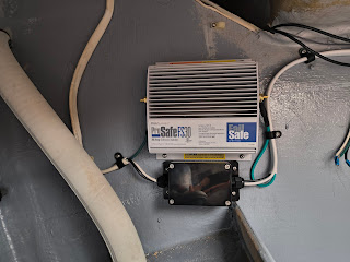
Replacing the plug was super easy, I just had to pull the old one off, disconnect the 3 AC wires that fee the AC panel and reconnect them to the new one. Since the new plug was a direct replacement of the old, I just had to plunk it back in place and bolt it on. While I was replacing that though, I remembered that I had a brand new galvanic isolator that came with the boat and even though I rarely (if ever) plug into shore power, I figured I might as well install it while I was in there. Since it was still too cold to do any caulking so I decided to tackle that.A galvanic isolator is essentially a box with several diodes in it that blocks stray DC current on the AC safety ground when connected to shore power. I don't fully understand the galvanic corrosion process, but I am all for reducing the possibility of corrosion on exposed underwater metals (shaft, prop, strut, etc...) and these devices are apparently helpful in preventing this. Plus, I had a new one in my shop (ProMariner ProSafeFS 30Amp).
Installation was straightforward and the hardest part was finding a good location between the shore power inlet and the AC panel and mounting the device in the fairly cramped lazarette. Wiring it only required cutting the AC cable and running the safety ground (green wire) through the isolator. I used a waterproof junction box to connect the wires coming from the shorepower inlet to a new AC cable (3 wire 10awg) that goes to the AC panel. The old cable had some signs of chafing and figured it would be best to replace it while I was in there.From there I spent a few hours bundling and securing the new wire in a run that terminates at the AC panel. This run goes from the galvanic isolator to a bulkhead and through the top of the engine compartment to the panel. I was really thankful that the engine is not installed yet or it would have been next to impossible to get it bundled, tidy, and well secured.
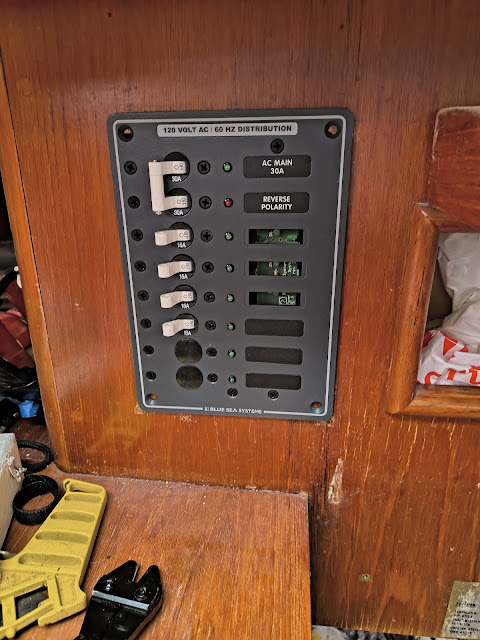
At this point I was fully immersed in the AC system and decided to just plow through and replace the old AC main panel with a new Blue Sea Systems double pole breaker panel (#8027). This would have been a straightforward job of just swapping out the old panel with the new if I hadn't decided to install the new ProMariner TruePower 1000w inverter to power the AC outlets with the battery when not connected to shorepower.
There are many ways to install an inverter in a boat and the easiest way is to install it inline between the shorepower and AC panel. However, if installed this way then when inverter is connected to the house batteries, it could potentially power all the AC circuits on the boat, including the battery charger. I'm not an electrical engineer, but I do know that you can't use battery power to run a charger to charge the battery. This would fall into the perpetual machine world and physics tells us that it isn't possible.
With this in mind, I decided to take another approach: install the inverter on a branch circuit that only powers the AC outlets. This is a common installation method as well, but because the AC outlets on Velorum were originally wired as 2 circuits (port and starboard), I decided to combine them into a single circuit downstream of the inverter.
The schematic below probably explains the AC portion of the installation circuit better than I can, but generally speaking the flow goes as follows:
- AC Shorepower -> Main Panel
- Main Panel circuit breaker -> Inverter
- Inverter -> Junction box that combines port and starboard outlets
 |
| AC Schematic |
 |
| Inverter Battery Disconnect and Monitor New Main AC Panel (almost installed) |


No comments:
Post a Comment