Monday, April 28, 2025

Backstay Chainplate

This project has been in the works since February, but it didn't all come together until this past weekend. It's part of the 'Get the decks waterproofed before I take the cover off project', but the backstay chainplate also falls in the project 'Make the rig strong' category.

I could have saved myself a lot of work by just bolting the old chainplate back in and calling it a day, but I had a few concerns about the strength of the almost 40 year old aluminum chainplate.  Unlike the stainless steel that makes up the shrouds and forestay chainplates, the fatigue strength of aluminum tends to decrease steadily with the number of stress cycles, and can fail with no warning signs.  Since the backstay is pretty critical to a boat's rig, I figured it was time to get a new chainplate made up.

I also found some water intrusion problems when inspecting the underdeck knee where the chainplate mounts.  The chainplate has four bolts that connect it to the knee and all of these holes clearly had some water damage and needed to be fixed.  Unfortunately, access to the knee is not great and requires getting into the lazarette and wriggling aft around the propane box to access.  I decided on a 2 step approach to rectify the problem.  

The first step was to overdrill all the existing chainplate holes (back to unsaturated wood), then fill the holes with structural epoxy and retapp.  The original bolts were 3/8" so I overdrilled with a 3/4" bit and found that there was no water ingress beyond that (phew).  I taped the backside of the holes and saturated the surrounding wood with unthickened epoxy.  Once that kicked, I filled the holes with thickened structural epoxy and used a small trowel to smooth out the side that was not taped.  

While all this was happening, I redesigned the chainplate in CAD so the new chainplate would have additional area that would connect further down the knee. Probably overkill given that the first one lasted almost 40 years, but it certainly wouldn't hurt to have additional connection points in the 'meat' of the knee.  I went through several iterations and 3d prints of the design to test fit before I sent the final version for machining.  

I contacted Mike Quill (the rigging foreman for Niagara when the boat was built) Mike Quill Yacht Rigging and as always, he got back to me very quickly and informed me that the original backstay chainplates were made of 6061-T6 with a hard anodized coating.  So I went with the same material and sent the design off to the machine shop (Xometry).  Three weeks later the shiny new part was in my hands and ready to install (cost was ~$210 shipped).

Once I had the new chainstay, I retapped the 4 holes that the original chainplate used and dry fitted the new chainplate.  Then I tapped the additional 5 holes to secure the new chainplate along the lower section of the knee.  I sanded everything down and then re-painted with epoxy bilge paint before bolting it all back together.  I had to enlist the help of my wife to get a wrench on the backing nuts while I tightened the bolts down with a socket.  I'm not sure how happy she was getting stuffed into the lazarette to perform extreme boat yoga, but she didn't complain.  

With the chainplate secured, I moved up on deck to seal off the opening.  I 3d printed a TPU (D95A) sleeve to go around the chainplate opening and then put down strips of butyl tape on top before screwing down the chainplate cover to compress the butyl tape and make a watertight seal.  Probably a lot of work and expense, but I won't be worrying about the backstay breaking loose on my watch.




Friday, April 18, 2025

One Thing Leads to Another

Despite my best efforts to get the decks waterproofed so that I can remove the cover, the past month has been way too cold to do much caulking so I turned to what I thought was a simple project that I could knock off in an afternoon.  The original shorepower inlet plug was pretty old and I could see cracking on the rubber gasket where it seats on the deck so if exposed to weather it would probably leak.  Since I had a brand new one in the shop, I figured I'd just replace it now because it didn't need caulking to waterproof it.

Of course, as with all things boat related simple things just seem to take way longer than expected especially when I'm working with 1-3 hour blocks of time that I can carve out.  You'd think I would learn after all these years working on boats. Nope.

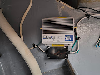
Replacing the plug was super easy, I just had to pull the old one off, disconnect the 3 AC wires that fee the AC panel and reconnect them to the new one. Since the new plug was a direct replacement of the old, I just had to plunk it back in place and bolt it on.  While I was replacing that though, I remembered that I had a brand new galvanic isolator that came with the boat and even though I rarely (if ever) plug into shore power, I figured I might as well install it while I was in there.  Since it was still too cold to do any caulking so I decided to tackle that.

A galvanic isolator is essentially a box with several diodes in it that blocks stray DC current on the AC safety ground when connected to shore power.  I don't fully understand the galvanic corrosion process, but I am all for reducing the possibility of corrosion on exposed underwater metals (shaft, prop, strut, etc...) and these devices are apparently helpful in preventing this.  Plus, I had a new one in my shop (ProMariner ProSafeFS 30Amp).  

Installation was straightforward and the hardest part was finding a good location between the shore power inlet and the AC panel and mounting the device in the fairly cramped lazarette.  Wiring it only required cutting the AC cable and running the safety ground (green wire) through the isolator.  I used a waterproof junction box to connect the wires coming from the shorepower inlet to a new AC cable (3 wire 10awg) that goes to the AC panel.  The old cable had some signs of chafing and figured it would be best to replace it while I was in there.

From there I spent a few hours bundling and securing the new wire in a run that terminates at the AC panel. This run goes from the galvanic isolator to a bulkhead and through the top of the engine compartment to the panel.  I was really thankful that the engine is not installed yet or it would have been next to impossible to get it bundled, tidy, and well secured.

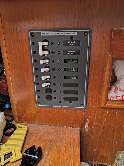
At this point I was fully immersed in the AC system and decided to just plow through and replace the old AC main panel with a new Blue Sea Systems double pole breaker panel (#8027).  This would have been a straightforward job of just swapping out the old panel with the new if I hadn't decided to install the new ProMariner TruePower 1000w inverter to power the AC outlets with the battery when not connected to shorepower.  

There are many ways to install an inverter in a boat and the easiest way is to install it inline between the shorepower and AC panel. However, if installed this way then when inverter is connected to the house batteries, it could potentially power all the AC circuits on the boat, including the battery charger.  I'm not an electrical engineer, but I do know that you can't use battery power to run a charger to charge the battery.  This would fall into the perpetual machine world and physics tells us that it isn't possible.  

With this in mind, I decided to take another approach: install the inverter on a branch circuit that only powers the AC outlets.  This is a common installation method as well, but because the AC outlets on Velorum were originally wired as 2 circuits (port and starboard), I decided to combine them into a single circuit downstream of the inverter.  

The schematic below probably explains the AC portion of the installation circuit better than I can, but generally speaking the flow goes as follows:

  1. AC Shorepower -> Main Panel
  2. Main Panel circuit breaker -> Inverter
  3. Inverter -> Junction box that combines port and starboard outlets
For the installation, I built a shelf in a compartment underneath the quarter berth next to the battery compartment and ran the AC cable from the panel along with positive and negative 2awg battery cables from the battery bank.  All of these connect to the inverter and depending on the power source, it sends AC power out of the compartment to a waterproof junction box mounted in the engine compartment and combines the port and starboard outlet circuits.

All in this took about 2 weeks of replacing the AC panel, running cable, building a shelf, securing cables, and connecting the junction box before it all came together.  A lot of work that all started because I decided to replace the shorepower inlet plug!

AC Schematic


Inverter Battery Disconnect and Monitor


New Main AC Panel (almost installed)


Inverter Installed 


Junction Box Combining Port and Starboard Outlets